Camera Protocol v2
The camera protocol v2 is used to configure camera payloads and request their status. It provides basic methods for photo capture, video capture and streaming, setting zoom and focus, querying and configuring camera storage, and selecting multiple cameras. It also defines a camera definition file format that allows a GCS to generate a configuration UI for setting any property of the camera using parameters.
INFO
This protocol supersedes Camera Protocol v1 (Simple Trigger Protocol). The older protocol enables camera triggering, but does not support other features or querying camera capabilities.
WARNING
We are transitioning from specific request commands to a single generic requestor. GCS and MAVLink SDKs/apps should support both approaches as we migrate to exclusive use of the new method (documented here). For more information see Migration Notes for GCS & Camera Servers.
MAVLink Camera Implementations
Camera Managers provide a MAVLink Camera protocol interface for cameras that don't directly implement MAVLink support. These generally run on a companion computer:
- MAVLink Camera Manager (actively maintained)
- Dronecode Camera Manager
- SIYI A8 mini camera manager - MAVSDK-plugin based camera manager for the SIYI A8 mini (includes tutorial).
These cameras have inbuilt support for MAVLink (but not necessarily camera protocol v2):
- PhaseOne Cameras (source).
- Workswell cameras: WIRIS Pro, WIRIS Pro SC, WIRIS Security, WIRIS Agro, GIS-320 (source).
Camera Addressing
MAVLink cameras are identified and addressed by their system and component id.
Components that have non-MAVLink cameras attached, such as companion computers, are expected expose each of them as a separate MAVLink camera component with its own HEARTBEAT.
The exception is the autopilot component, which can "proxy" up to 6 attached non-MAVLink cameras: these are identified by a camera_device_id field in messages and Target Camera ID label in commands.
Camera Messages
All MAVLink components include their system id and component id fields in the MAVLink packet header when sending messages. As each MAVLink camera component (with HEARTBEAT.type=MAV_TYPE_CAMERA) represents just one camera, these ids can be used to uniquely identify the camera associated with a message.
non-MAVLink cameras attached to the autopilot are identified first by the autopilot system/component id, and then by a camera_device_id field in the message payload (all camera messages should have an id field with this or a similar name). An autopilot should set this to the id of the associated camera device, and otherwise this should always be set to zero.
Camera Addressing in Commands
MAVLink cameras are sent commands addressed using their system and component ids (just as when addressing commands to any other component).
To send commands to autopilot-attached cameras, the command should be send to the autopilot component. The device id of the target attached camera must further be set in the command's Target Camera ID parameter (the index and precise label of this parameter may vary). The autopilot is required to respond to the command with COMMAND_ACK, populating the COMMAND_ACK.result_param2 field with the id of the targeted autopilot connected camera, if any.
Note that the Target Camera ID parameter should be set to 0 in order to target all cameras, or if targeting a MAVLink camera.
Camera Addressing in Missions
When using a camera MAV_CMD in a mission, the id parameter (if present) indicates the target camera:
- 1 - 6 indicates a flight-stack connected camera
- 7-255 is the component id of a MAVLink connected camera. Note that component ids 1-6 should never be used for MAVLink cameras!
- 0 indicates "all connected cameras".
When processing a camera item in a mission the autopilot should:
- For
Target Camera IDvalues of1-6, perform the specified camera action on the connected camera if it exists, and otherwise log an error. - For other
Target Camera IDvalues, re-emit theMAV_CMDusing the command protocol, setting the target component id to theidset in the camera mission item. It should also log any errors from the returnedCOMMAND_ACK.
INFO
Flight stacks that predate using a camera id typically re-emit the mission command addressed either to the broadcast component id (0) or to MAV_COMP_ID_CAMERA. The former triggers all cameras on the system, while the later provides better command handling because there is only one COMMAND_ACK.
Camera Discovery
Connection
MAVLink Camera components are expected to follow the Heartbeat/Connection Protocol and sent a constant flow of heartbeats (nominally at 1Hz). Cameras must set a HEARTBEAT.type of MAV_TYPE_CAMERA. Each camera must use a different pre-defined camera component ID. Values of MAV_COMP_ID_CAMERA to MAV_COMP_ID_CAMERA6 are recommended, but in theory any camera ID may be used except for 0 to 6 (which are reserved for cameras proxied by another component, such as the autopilot).
A GCS should start the Camera Identification process the first time it detects a HEARTBEAT from a new:
- MAVLink camera component.
- Autopilot, in order to detect autopilot-connected cameras.
INFO
If a receiving system stops receiving heartbeats from the camera it is assumed to be disconnected, and should be removed from the list of available cameras. If heartbeats are again detected, the camera identification process below must be restarted from the beginning.
INFO
If a vehicle has more than one MAVLink camera, each camera will have a different component ID and send its own heartbeat. The vehicle autopilot might also have directly connected cameras, which are separately addressed by a camera device id. The GCS should create multiple instances of a camera controller based on the component ID of each camera, and also the component ID of the autopilot and each of its attached camera devices. All commands are sent to a specific camera by addressing the command to a specific component ID, and additionally the camera device id for autopilots.
Camera Identification
The camera identification operation identifies all the available cameras associated with a system and determines their capabilities. It is used to discover both MAVLink cameras and non-MAVLink cameras attached to the autopilot.
The process involves requesting the CAMERA_INFORMATION message from autopilots and MAVLink cameras as they are discovered. CAMERA_INFORMATION.flags provides information about camera capabilities. It contains a bitmap of CAMERA_CAP_FLAGS values that tell the GCS if the camera supports still image capture, video capture, or video streaming, and if it needs to be in a certain mode for capture, etc.
TIP
Camera identification must be carried out before all other camera operations!
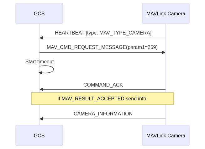
The first time a heartbeat is received from a new camera component (HEARTBEAT.type=MAV_TYPE_CAMERA), the GCS should send it a MAV_CMD_REQUEST_MESSAGE message asking for CAMERA_INFORMATION (message id 259). The camera will then respond with the a COMMAND_ACK message containing a result. On success (result is MAV_RESULT_ACCEPTED) the camera component must then send a CAMERA_INFORMATION message.
The operation follows the normal Command Protocol rules for command/acknowledgment (if no COMMAND_ACK response is received for MAV_CMD_REQUEST_MESSAGE the command will be re-sent a number of times before failing). If CAMERA_INFORMATION is not received after receiving an ACK with MAV_RESULT_ACCEPTED, the protocol assumes the message was lost, and the cycle of sending MAV_CMD_REQUEST_MESSAGE is repeated. If CAMERA_INFORMATION is still not received after three cycle repeats, the GCS may assume that the camera is not supported.
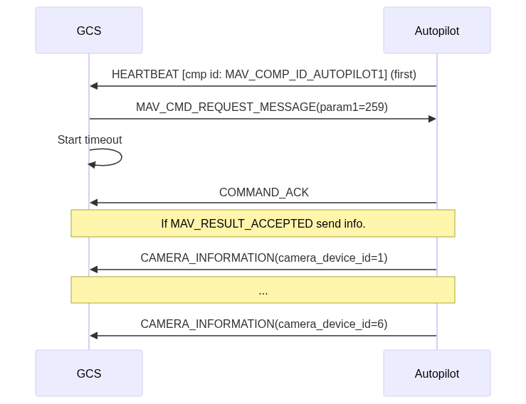
The first time a heartbeat is received from an autopilot, the GCS follow the same process to query for information about directly connected cameras. The only difference is that the autopilot should return a CAMERA_INFORMATION message for each connected camera, populated with its camera_device_id.
Additional Camera Information
The CAMERA_INFORMATION response contains the bare minimum information about the camera and what it can or cannot do. This is sufficient for basic image and/or video capture.
If a camera provides finer control over its settings CAMERA_INFORMATION.cam_definition_uri will include a URI to a Camera Definition File. If this URI exists, the GCS will request it, parse it and prepare the UI for the user to control the camera settings.
The CAMERA_INFORMATION.cam_definition_version field should provide a version for the definition file, allowing the GCS to cache it. Once downloaded, it would only be requested again if the version number changes.
INFO
A GCS that implements this protocol is expected to support both HTTP (http://) and MAVLink FTP (mftp://) URIs for download of the camera definition file. If the camera provides an HTTP or MAVLink FTP interface, the definition file can be hosted on the camera itself. Otherwise, it can be hosted anywhere (on any reachable server).
Basic Camera Operations
Camera Modes
Some cameras must be in a certain mode for still and/or video capture.
The GCS can determine if it needs to make sure the camera is in the proper mode prior to sending a start capture (image or video) command by checking whether the CAMERA_CAP_FLAGS_HAS_MODES bit is set true in CAMERA_INFORMATION.flags.
In addition, some cameras can capture images in any mode but with different resolutions. For example, a 20 megapixel camera would take a full resolution image when set to CAMERA_MODE_IMAGE but only at the current video resolution if it is set to CAMERA_MODE_VIDEO.
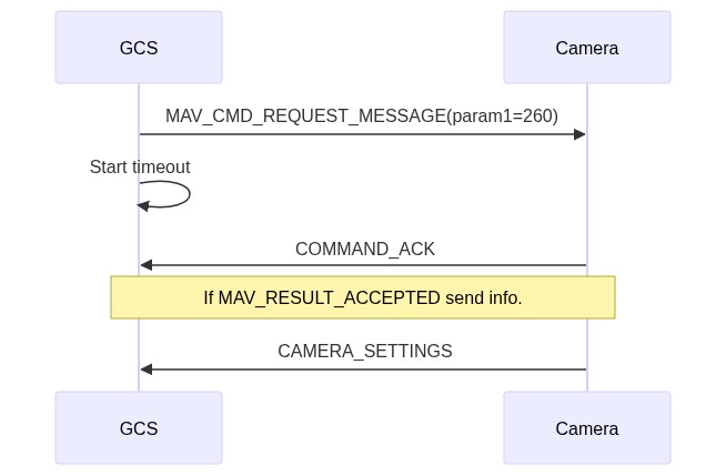
To get the current mode, the GCS would send a MAV_CMD_REQUEST_MESSAGE command asking for CAMERA_SETTINGS. The camera component will then respond with the COMMAND_ACK message containing a result. On success (COMMAND_ACK.result is MAV_RESULT_ACCEPTED) the camera must then send a CAMERA_SETTINGS message. The current mode is the CAMERA_SETTINGS.mode_id field.
The sequence is shown below:
INFO
Command acknowledgment and message resending is handled in the same way as for camera identification (if a successful ACK is received the camera will expect the CAMERA_SETTINGS message, and repeat the cycle - up to 3 times - until it is received).
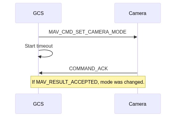
To set the camera to a specific mode, the GCS would send the MAV_CMD_SET_CAMERA_MODE command with the appropriate mode.
The sequence is shown below:
INFO
The operation follows the normal Command Protocol rules for command/acknowledgment.
Storage Status
Before capturing images and/or videos, a GCS should query the storage status to determine if the camera has enough free space for these operations (and provide the user with feedback as to the current storage status). The GCS will send the MAV_CMD_REQUEST_MESSAGE command and it expects a COMMAND_ACK message back as well as a STORAGE_INFORMATION response. For formatting (or erasing depending on your implementation), the GCS will send a MAV_CMD_STORAGE_FORMAT command.
Camera Capture Status
In addition to querying about storage status, the GCS should also stream the Camera Capture Status in order to provide the user with proper UI indicators.
This can be done by sending a MAV_CMD_SET_MESSAGE_INTERVAL command asking for CAMERA_CAPTURE_STATUS. The command it expects a COMMAND_ACK message back and then CAMERA_CAPTURE_STATUS should be streamed at the specified rate.
Still Image Capture
A camera supports still image capture if the CAMERA_CAP_FLAGS_CAPTURE_IMAGE bit is set in CAMERA_INFORMATION.flags.
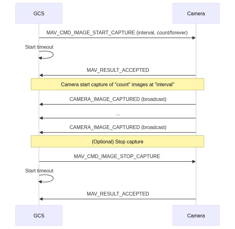
A GCS/MAVLink app uses the MAV_CMD_IMAGE_START_CAPTURE command to request that the camera capture a specified number of images (or forever), and the duration between them. The camera immediately returns the normal command acknowledgment (MAV_RESULT).
Each time an image is captured, the camera broadcasts a CAMERA_IMAGE_CAPTURED message. This message not only tells the GCS the image was captured, it is also intended for geo-tagging.
INFO
The camera must iterate CAMERA_IMAGE_CAPTURED.image_index and the counter used in CAMERA_CAPTURE_STATUS.image_count for every new image capture (these values iterate until explicitly cleared using MAV_CMD_STORAGE_FORMAT). The index and total image count can be used to re-request missing images (e.g. images captured when the vehicle was out of telemetry range).
The MAV_CMD_IMAGE_STOP_CAPTURE command can optionally be sent to stop an image capture sequence (this is needed if image capture has been set to continue forever).
The still image capture message sequence for missions (as described above) is shown below:
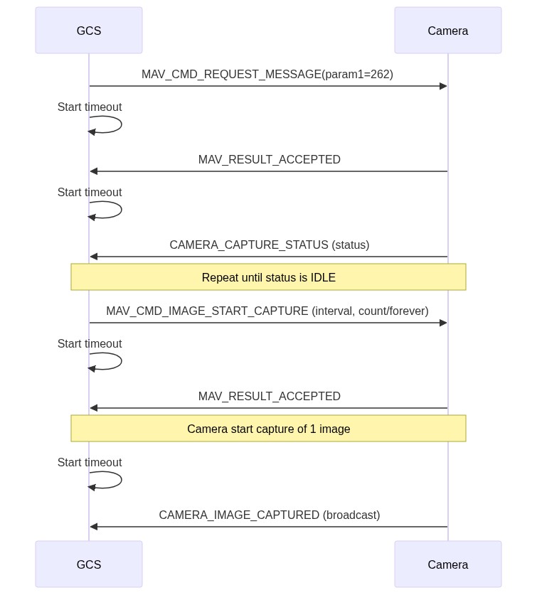
The message sequence for interactive user-initiated image capture through a GUI is slightly different. In this case the GCS should:
- Confirm that the camera is ready to take images before allowing the user to request image capture.
- It does this by by sending MAV_CMD_REQUEST_MESSAGE asking for CAMERA_CAPTURE_STATUS.
- The camera should return a
MAV_RESULTand then CAMERA_CAPTURE_STATUS. - The GCS should check that the status is "Idle" before enabling camera capture in the GUI.
- Send MAV_CMD_IMAGE_START_CAPTURE specifying a single image (only).
The sequence is as shown below:
Request Lost CAMERA_IMAGE_CAPTURED Messages
The camera broadcasts a CAMERA_IMAGE_CAPTURED every time a new image is captured, iterating both the current image index (CAMERA_IMAGE_CAPTURED.image_index) and the total image count (CAMERA_CAPTURE_STATUS.image_count).
These messages can be lost during transmission; for example if the vehicle is out of data-link range of the ground stations.
Lost image capture messages can be detected by comparing GCS and camera image counts. Individual entries can be requested using MAV_CMD_REQUEST_MESSAGE, where param1="MAVLINK_MSG_ID_CAMERA_IMAGE_CAPTURED" and param2="the index of the missing image".
The camera image log iterates "forever" (but may be explicitly reset using MAV_CMD_STORAGE_FORMAT.param3=1).
Video Capture
A camera supports video capture if the CAMERA_CAP_FLAGS_CAPTURE_VIDEO bit is set in CAMERA_INFORMATION.flags.
To start recording videos, the GCS uses the MAV_CMD_VIDEO_START_CAPTURE command. If requested, the CAMERA_CAPTURE_STATUS message is sent to the GCS at a set interval.
To stop recording, the GCS uses the MAV_CMD_VIDEO_STOP_CAPTURE command.
Video Streaming
INFO
The GCS should already have identified all connected cameras by their heartbeat and followed the Camera Identification steps to get CAMERA_INFORMATION for every camera.
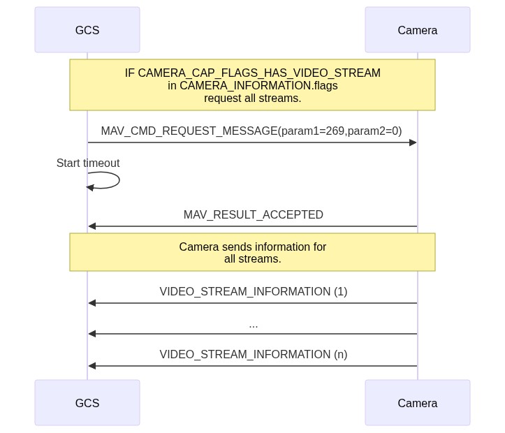
A camera is capable of streaming video if it sets the CAMERA_CAP_FLAGS_HAS_VIDEO_STREAM bit set in CAMERA_INFORMATION.flags.
The sequence for requesting all video streams from a particular camera is shown below:
The steps are:
GCS follows the Camera Identification steps to get CAMERA_INFORMATION for every camera.
GCS checks if CAMERA_INFORMATION.flags contains the CAMERA_CAP_FLAGS_HAS_VIDEO_STREAM flag.
If so, the GCS sends the MAV_CMD_REQUEST_MESSAGE message to the camera requesting the video streaming configuration (
param1=269) for all streams (param2=0).INFO
A GCS can also request information for a particular stream by setting its id in
param2.Camera returns a VIDEO_STREAM_INFORMATION message for the specified stream or all streams it supports.
INFO
If your camera only provides video streaming and nothing else (no camera features), the CAMERA_CAP_FLAGS_HAS_VIDEO_STREAM flag is the only flag you need to set. The GCS will then provide video streaming support and skip camera control.
Video Metadata
The protocol provides some information about video streaming support in CAMERA_CAP_FLAGS, such as support for video streaming (CAMERA_CAP_FLAGS_HAS_VIDEO_STREAM) and thermal range information (CAMERA_CAP_FLAGS_HAS_THERMAL_RANGE), In addition the VIDEO_STREAM_INFORMATION and VIDEO_STREAM_STATUS provide broad information about each stream, including its transport mechanism, encoding, resolution, frame rate, and status (VIDEO_STREAM_STATUS_FLAGS).
MAVLink does not specify any mechanism for getting frame-synchronized video metadata, such as absolute thermal values of thermal video streams, text-tracks, and so on. The following sections outline some MAVLink-centric methods for getting "approximate" video-synchronized metadata.
Camera absolute thermal range
A thermal video stream is often coloured as a heatmap in order to highlight hotter and colder sections. This heatmap is relative to the hottest and coldest points on the frame, so the hot sections are not necessarily hot, they are just hotter than their surroundings. If you're searching for things that have a specific temperature, it can be useful to know the absolute temperatures represented by the image.
The CAMERA_THERMAL_RANGE message can be streamed alongside a video stream to provide this information. The message includes the associated stream and camera id, along with the position and value of the maximum and minimum temperature in the video frame. That is sufficient to overlay the hottest and coldest points on a video, and in theory to determine the absolute temperature of all pixels.
INFO
The message is streamed alongside the video stream, but there is no precise mechanism to synchronize values to frames. The information is therefore an estimate/approximate.
The message can be requested for a particular camera and stream using the MAV_CMD_SET_MESSAGE_INTERVAL, when the associated VIDEO_STREAM_STATUS.flag for the stream has bit VIDEO_STREAM_STATUS_FLAGS_THERMAL_RANGE_ENABLED set. Note that MAV_CMD_SET_MESSAGE_INTERVAL.param3 indicates the stream id of the current camera, or 0 for all streams, while param4 indicates the target camera_device_id for autopilot-attached cameras or 0 for MAVLink cameras.
Camera Tracking
A camera may support tracking a point and/or a rectangle. Information about the tracked point can be streamed during tracking, and may be passed to a gimbal in order to move the camera to track the target (or control vehicle attitude to track the target).
Support for tracking different types of targets is indicated by the CAMERA_CAP_FLAGS_HAS_TRACKING_POINT and/or CAMERA_CAP_FLAGS_HAS_TRACKING_RECTANGLE flags in CAMERA_INFORMATION.flags.
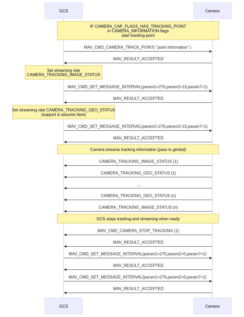
To start camera tracking a GCS uses either the MAV_CMD_CAMERA_TRACK_POINT or MAV_CMD_CAMERA_TRACK_RECTANGLE command.
After starting camera tracking you should call MAV_CMD_SET_MESSAGE_INTERVAL to start streaming the CAMERA_TRACKING_IMAGE_STATUS message at your desired rate. This message contains information about the tracked point/rectangle in an image, and may be used by the receiving system to determine the location of the target (alongside other information like the CAMERA_FOV_STATUS).
If geo-tracking status information is supported (indicated by CAMERA_CAP_FLAGS_HAS_TRACKING_GEO_STATUS) you should also call MAV_CMD_SET_MESSAGE_INTERVAL to stream CAMERA_TRACKING_GEO_STATUS at your desired rate. This message provides the location of the target in physical co-ordinates that can be passed to a gimbal.
To stop any kind of tracking, a GCS uses the MAV_CMD_CAMERA_STOP_TRACKING command. After stopping tracking you should call MAV_CMD_SET_MESSAGE_INTERVAL to stop streaming CAMERA_TRACKING_IMAGE_STATUS and CAMERA_TRACKING_GEO_STATUS (set their rates to 0).
Camera tracking message sequence
INFO
The GCS should already have identified all connected cameras by their heartbeat and followed the Camera Identification steps to get CAMERA_INFORMATION for every camera.
The sequence for tracking a point is shown below (tracking a rectangle is the same sequence but a different tracking command).
The steps are:
- GCS follows the Camera Identification steps to get CAMERA_INFORMATION for every camera.
- GCS checks if CAMERA_INFORMATION.flags contains the
CAMERA_CAP_FLAGS_HAS_TRACKING_RECTANGLE,CAMERA_CAP_FLAGS_HAS_TRACKING_POINT,CAMERA_CAP_FLAGS_HAS_TRACKING_GEO_STATUS. - If tracking is supported the GCS sends the command to start the type of tracking it wants to do: MAV_CMD_CAMERA_TRACK_POINT or MAV_CMD_CAMERA_TRACK_RECTANGLE. The sequence above just shows point tracking.
- Set the desired rates (intervals) for streaming the tracking status messages.
- Camera streams CAMERA_TRACKING_IMAGE_STATUS and/or CAMERA_TRACKING_GEO_STATUS. These are used to provide camera targetting information.
- To stop tracking, a GCS uses the MAV_CMD_CAMERA_STOP_TRACKING command. The streaming intervals must also be set to zero.
Battery Status
Camera components that are powered from their own battery should publish BATTERY_STATUS messages.
Other components like a GCS will typically only use the camera BATTERY_STATUS.battery_remaining field (or possibly time_remaining); generally other fields can be set as "not supported".
Message/Command/Enum Summary
Messages
| Message | Description |
|---|---|
| CAMERA_INFORMATION | Basic information about camera including supported features and URI link to extended information (cam_definition_uri field). |
| CAMERA_SETTINGS | Timestamp and camera mode information. |
| VIDEO_STREAM_INFORMATION | Information defining a video stream configuration. If a camera has more than one video stream, it would send one of this for each video stream, with their specific configuration. Each stream must have its own, unique stream_id. |
| VIDEO_STREAM_STATUS | Information updating a video stream configuration. |
| STORAGE_INFORMATION | Storage information (e.g. number and type of storage devices, total/used/available capacity, read/write speeds). |
| CAMERA_CAPTURE_STATUS | Camera capture status, including current capture type (if any), capture interval, available capacity. |
| CAMERA_IMAGE_CAPTURED | Information about image captured (returned to GPS every time an image is captured). |
| CAMERA_FOV_STATUS | Information about the field of view of a camera. Requested using MAV_CMD_REQUEST_MESSAGE. |
| CAMERA_TRACKING_IMAGE_STATUS | Camera tracking status, sent while in active tracking. Use MAV_CMD_SET_MESSAGE_INTERVAL to define message interval. |
| CAMERA_TRACKING_GEO_STATUS | Camera tracking status, sent while in active tracking. Use MAV_CMD_SET_MESSAGE_INTERVAL to define message interval. |
| CAMERA_THERMAL_RANGE | Camera absolute thermal range. This provides value and position of max/min temperature in a video stream, allowing thermal range of video to be calibrated to absolute rather than relative temperature. Use MAV_CMD_SET_MESSAGE_INTERVAL to define message interval for a particular camera and stream. |
Commands
| Command | Description |
|---|---|
| MAV_CMD_REQUEST_MESSAGE | Send command to request any message (used to request CAMERA_INFORMATION and the other messages above) |
| MAV_CMD_SET_CAMERA_MODE | Send command to set CAMERA_MODE. |
| MAV_CMD_SET_CAMERA_ZOOM | Send command to set the camera zoom. |
| MAV_CMD_SET_CAMERA_FOCUS | Send command to set the camera focus. |
| MAV_CMD_IMAGE_START_CAPTURE | Send command to start image capture, specifying the duration between captures and total number of images to capture. |
| MAV_CMD_IMAGE_STOP_CAPTURE | Send command to stop image capture. |
| MAV_CMD_VIDEO_START_CAPTURE | Send command to start video capture, specifying the frequency that CAMERA_CAPTURE_STATUS messages should be sent while recording. |
| MAV_CMD_VIDEO_STOP_CAPTURE | Send command to stop video capture. |
| MAV_CMD_VIDEO_START_STREAMING | Send command to start video streaming for the given Stream ID (stream_id.) This is mostly for streaming protocols that push a stream. If your camera uses a connection based streaming configuration (RTSP, TCP, etc.), you may ignore it if you don't need it but note that you still must ACK the command, like all MAV_CMD_XXX commands. When using a connection based streaming configuration, the GCS will connect the stream from its side. When a camera offers more than one stream and the user switches from one stream to another, the GCS will send a MAV_CMD_VIDEO_STOP_STREAMING command targeting the current Stream ID followed by a MAV_CMD_VIDEO_START_STREAMING targeting the newly selected Stream ID. |
| MAV_CMD_VIDEO_STOP_STREAMING | Send command to stop video streaming for the given Stream ID (stream_id.) This is mostly for streaming protocols that push a stream. If your camera uses a connection based streaming configuration (RTSP, TCP, etc.), you may ignore it if you don't need it but note that you still must ACK the command, like all MAV_CMD_XXX commands. When using a connection based streaming configuration, the GCS will disconnect the stream from its side. When a camera offers more than one stream and the user switches from one stream to another, the GCS will send a MAV_CMD_VIDEO_STOP_STREAMING command targeting the current Stream ID followed by a MAV_CMD_VIDEO_START_STREAMING targeting the newly selected Stream ID. |
| MAV_CMD_CAMERA_TRACK_POINT | Initate visual point tracking, if supported by the camera (CAMERA_CAP_FLAGS_HAS_TRACKING_POINT is set). |
| MAV_CMD_CAMERA_TRACK_RECTANGLE | Initiate visual rectangle tracking, if supported by the camera (CAMERA_CAP_FLAGS_HAS_TRACKING_RECTANGLE is set). |
| MAV_CMD_CAMERA_STOP_TRACKING | Stop camera tracking (as initiated using MAV_CMD_CAMERA_TRACK_POINT or MAV_CMD_CAMERA_TRACK_RECTANGLE). |
Deprecated Commands
These commands have been deprecated, replaced by the generic requester command MAV_CMD_REQUEST_MESSAGE
| Command | Description |
|---|---|
| MAV_CMD_REQUEST_CAMERA_SETTINGS | Send command to request CAMERA_SETTINGS. |
| MAV_CMD_REQUEST_CAMERA_INFORMATION | Send command to request CAMERA_INFORMATION. |
| MAV_CMD_REQUEST_VIDEO_STREAM_INFORMATION | Send command to request VIDEO_STREAM_INFORMATION. This is sent once for each camera when a camera is detected and it has set the CAMERA_CAP_FLAGS_HAS_VIDEO_STREAM flag within the CAMERA_INFORMATION message flags field. |
| MAV_CMD_REQUEST_VIDEO_STREAM_STATUS | Send command to request VIDEO_STREAM_STATUS. This is sent whenever there is a mode change (when MAV_CMD_SET_CAMERA_MODE is sent.) It allows the camera to update the stream configuration when a camera mode change occurs. |
| MAV_CMD_REQUEST_STORAGE_INFORMATION | Send command to request STORAGE_INFORMATION. |
| MAV_CMD_REQUEST_CAMERA_CAPTURE_STATUS | Send command to request CAMERA_CAPTURE_STATUS. |
Enum
| Enum | Description |
|---|---|
| CAMERA_CAP_FLAGS | Camera capability flags (Bitmap). For example: ability to capture images in video mode, support for survey mode etc. Received in CAMERA_INFORMATION. |
| CAMERA_MODE | Camera mode (image, video, survey etc.). Received in CAMERA_SETTINGS. |
| VIDEO_STREAM_TYPE | Type of stream - e.g. RTSP, MPEG. Received in VIDEO_STREAM_INFORMATION. |
| VIDEO_STREAM_STATUS_FLAGS | Bitmap of stream status flags - e.g. zoom, thermal imaging, etc. Received in VIDEO_STREAM_INFORMATION. |
| CAMERA_TRACKING_STATUS_FLAGS | Current tracking status. Received in CAMERA_TRACKING_IMAGE_STATUS amd CAMERA_TRACKING_GEO_STATUS. |
| CAMERA_TRACKING_MODE | Current tracking mode. Received in CAMERA_TRACKING_IMAGE_STATUS. |
| CAMERA_TRACKING_TARGET_DATA | Indicates how target data is encoded in image. Received in CAMERA_TRACKING_IMAGE_STATUS. |
Migration Notes for GCS & MAVLink SDKs
The original definition of this protocol used specific commands to query for each type of information requested from the camera: MAV_CMD_REQUEST_CAMERA_INFORMATION (for CAMERA_INFORMATION), MAV_CMD_REQUEST_CAMERA_SETTINGS, MAV_CMD_REQUEST_CAMERA_CAPTURE_STATUS, MAV_CMD_REQUEST_VIDEO_STREAM_INFORMATION, MAV_CMD_REQUEST_STORAGE_INFORMATION.
The latest version replaces all of these specific commands with the general requestor MAV_CMD_REQUEST_MESSAGE.
The transition works like this:
- Cameras need to handle both approaches for now (i.e. support both new generic and old specific commands).
- Ground stations will move from using the old specific commands to using both. They can try the new one and if they don't get an answer within a timeout they need to fall back to the previous command.
- After the new commands have been established in server and ground stations, the old specific commands may be removed from the implementations.


