Gimbal Protocol (v2)
INFO
This version supersedes Gimbal Protocol v1 Existing functionality is now fixed, but compatible changes may still be added.
Introduction
The gimbal protocol allows MAVLink control over the attitude/orientation of cameras (or other sensors) mounted on the drone. The orientation can be: controlled by the pilot in real time (e.g. using a joystick from a ground station), set as part of a mission, or moved based on camera tracking.
The protocol also defines what status information is published for developers, configurators, as well as users of the drone. It additionally provides ways to assign control to different sources.
The protocol supports a number of hardware setups, and enables gimbals with varying capabilities.
INFO
The original protocol design document can be found here.
Concepts
Gimbal Manager and Gimbal Device
To accommodate gimbals with varying capabilities, and various hardware setups, "a gimbal" is conceptually split into two parts:
- Gimbal Device: the actual gimbal device, hardware and software.
- Gimbal Manager: software to deconflict gimbal messages and commands from different sources, and to abstract the capabilities of the Gimbal Device from gimbal users.
The Gimbal Manager and Gimbal Device expose respective message sets that can be used for: gimbal manager/device discovery, querying capabilities, publishing status, and various types of orientation/attitude control.
The key concept to understand is that a Gimbal Manager has a 1:1 relationship with a particular Gimbal Device, and is the only party on the MAVLink network that is allowed to directly command that device - it does so using the Gimbal Device message set.
INFO
The Gimbal Device must act only upon messages that come from the associated Gimbal Manager! The device will however broadcast its status to all parties on the network (not just its manager).
MAVLink applications (ground stations, developer APIs like the MAVSDK, etc.), and any other software that wants to control a particular gimbal, must do so via its Gimbal Manager, using the Gimbal Manager message set.
Note that the gimbal manager is (by default) implemented on the autopilot.
Common Set-ups
This section outlines the three most common hardware set-ups.
Simple Gimbal Directly Connected to Autopilot
In this (default) set-up the autopilot takes the role of the gimbal manager.

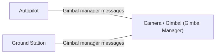
Standalone Integrated Camera/Gimbal
In this set-up the integrated camera/gimbal itself can be the Gimbal Manager.
Therefore, the gimbal device interface is internal (no implementation is required).
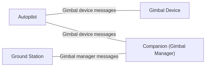
Onboard Computer with Gimbal Connected to Autopilot
In this set-up the Gimbal Manager can be on the onboard computer.
Commands from the GCS (etc.) are sent to the Gimbal Manager on the companion computer. Messages from the Gimbal Manager to the Gimbal Device need to be sent to/routed through the autopilot.
Multiple Gimbals
Multiple gimbals per drone are supported.
Component IDs
Multiple component IDs are reserved for MAVLink gimbal devices: MAV_COMP_ID_GIMBAL, MAV_COMP_ID_GIMBAL2, MAV_COMP_ID_GIMBAL3, MAV_COMP_ID_GIMBAL4, MAV_COMP_ID_GIMBAL5, MAV_COMP_ID_GIMBAL6.
The listed component IDs should be used where possible. Ids 0-6 may not be used. Other ids may be used as long as the MAV_TYPE is correctly set to MAV_TYPE_GIMBAL.
Mapping from Gimbal Managers to Gimbal Devices
Every Gimbal Manager has a single associated Gimbal Device that it controls (there is a 1:1 relationship). A particular MAVLink component, such as an autopilot, can implement multiple gimbal managers in order to control two or more gimbal devices. The identity of a gimbal device and its associated manager, are represented by a "gimbal device id". This id is used to differentiate messages from different gimbal managers, and also to target a particular gimbal in commands/messages sent to the component that is hosting its gimbal manager.
A Gimbal Manager publishes the id of its associated device in the gimbal_device_id field of the GIMBAL_MANAGER_INFORMATION message (this same field name is present in all gimbal manager messages so you can identify the source). Similarly, commands that can be sent to a gimbal manager include a parameter with label Gimbal device ID that indicates the particular gimbal manager (and device).
- A system that wants to control a particular gimbal device will send messages to the component that has the manager(s), such as an autopilot, specifying the device id of the gimbal to be controlled.
- A system that wants to control all gimbal devices managed by gimbal managers on a particular component, would send the command/message to that component and set the device id to
0.
Addressing of Gimbal MAVLink Devices
For MAVLink gimbal devices the gimbal device id (gimbal_device_id) is the MAVLink component ID of the gimbal device controlled by the gimbal manager.
The gimbal manager processes commands for its associated device, sending appropriate/corresponding gimbal device commands to the MAVLink gimbal device.
Addressing of non-MAVLink gimbal devices
Non-MAVLink gimbal devices are gimbals that don't expose a MAVLink Gimbal Device (or manager) API, but instead are connected to the gimbal manager using some other protocol. For instance, this could be a PWM gimbal connected to an autopilot. Since the gimbal device is not a MAVLink component, it does not have a unique MAVLink component ID that can be used for the gimbal device id. Therefore you either have to make it into a MAVLink component (so it has an id) or assign it a particular non-MAVLink id.
Autopilots are expected to implement gimbal managers for each attached gimbal and assign each a unique gimbal device id between 1 and 6 (which is why these values can't be used as MAVLink component IDs for gimbal devices). This id would then be used in gimbal manager messages sent by the autopilot, and for addressing the particular gimbal in commands. The autopilot would directly control attached gimbals in response to gimbal manager commands. In addition to sending gimbal manager messages when appropriate, it should also send/stream required gimbal device messages, such as GIMBAL_DEVICE_ATTITUDE_STATUS.
All other hardware with attached gimbal devices, such as a companion computers, are expected to implement them as separate MAVLink components, with their own MAVLink component ID that can be used for addressing. For example, a companion computer with an attached gimbal would appear as two MAVLink components: a companion computer and a gimbal. The gimbal component would identify as a type MAV_TYPE_GIMBAL and assert that it implements the gimbal manager protocol. As with autopilot-attached cameras it would need to respond as a gimbal manager, and also stream required gimbal device messages.
INFO
Implementing each attached camera as a separate MAVLink component allows cameras attached to a companion computer to be separately addressed in missions executed on the autopilot.
Implementation and Messages
Messages between Ground Station and Gimbal Manager
Discovery of Gimbal Manager
A ground station should monitor for HEARTBEAT messages from all new components and check their capabilities by requesting AUTOPILOT_VERSION for autopilots and COMPONENT_INFORMATION_BASIC for other components (see HEARTBEAT/Connection protocol).
If the capabilities field of the above message(s) has the flag MAV_PROTOCOL_CAPABILITY_COMPONENT_IMPLEMENTS_GIMBAL_MANAGER set:
- GCS should send a MAV_CMD_REQUEST_MESSAGE to the component for GIMBAL_MANAGER_INFORMATION.
- Component should respond by emitting a
GIMBAL_MANAGER_INFORMATIONmessage for each gimbal manager that it implements.
The GIMBAL_MANAGER_INFORMATION contains important information a particular gimbal, such as its capabilities (GIMBAL_MANAGER_CAP_FLAGS), maximum angles and angle rates, as well as the gimbal_device_id which identifies the specific gimbal device controlled by a particular Gimbal Manager.
WARNING
A GCS should always request GIMBAL_MANAGER_INFORMATION from autopilot components prior to: PX4 v1.16, ArduPilot-4.5 (when the protocol bit was added).
Gimbal Manager Status
A Gimbal Manager should send out GIMBAL_MANAGER_STATUS at a low regular rate (e.g. 5 Hz) to inform the ground station about its status.
Starting / Configuring Gimbal Control
It is possible for multiple components to want to control a gimbal at the same time, e.g.: a ground station, a companion computer, or the autopilot running a mission.
In order to start controlling a gimbal, a component first needs to send the MAV_CMD_DO_GIMBAL_MANAGER_CONFIGURE command. This allows setting which MAVLink component (set by system ID and component ID) is in primary control and which one is in secondary control. The gimbal manager is to ignore any gimbal controls which come from MAVLink components that are not explicitly set to "in control". This should prevent conflicts between various inputs as long as all components are fair/co-operative when using the configure command.
To be co-operative entails the following rules:
- Don't send the configure manager configure command continuously but only once to initiate and once to stop control again.
- Check the GIMBAL_MANAGER_STATUS about who is in control first and - if possible - warn user about planned action. For example, if the autopilot is in control of the gimbal as part of a mission, the ground station should ask the user first (i.e. via a pop-up) if they really want to take over manual control.
- Don't forget to release control when an action/task is finished and set the sysid/compid to 0.
INFO
It is possible to assign control to another component too, not just to itself. For example, a smart shot running on a companion computer can set itself to be in primary control but assign a ground station for secondary control to e.g. nudge during the smart shot.
INFO
The implementation of how primary and secondary control are combined or mixed is not defined by the protocol but up to the implementation. This allows flexibility for different use cases.
Manual Gimbal Control using MAVLink
A ground station can manually control a gimbal by sending GIMBAL_MANAGER_SET_MANUAL_CONTROL. This allows controlling the gimbal with either angles, or angular rates, using a normalized unit (-1..1). The gimbal device is responsible for translating the input based on angle, speed, and "smoothness" settings.
This input can additionally be scaled by the gimbal manager depending on its state. For example, if the gimbal manager is on a camera and knows the current zoom level / focal length of the camera, it can scale the angular rate down to support smooth panning and tilting.
Controlling Gimbal Angle and/or Angular Rate using MAVLink
A ground station, companion computer, or other MAVLink component can set the gimbal angle and/or angular rates using the messages GIMBAL_MANAGER_SET_ATTITUDE or GIMBAL_MANAGER_SET_PITCHYAW.
Messages between Gimbal Manager and Gimbal Device
Discovery of Gimbal Device
The MAVlink node where the Gimbal Manager is implemented needs to discover Gimbal Devices by sending a broadcast MAV_CMD_REQUEST_MESSAGE for GIMBAL_DEVICE_INFORMATION. Every gimbal device should respond with GIMBAL_DEVICE_INFORMATION.
The MAVLink node should then create as many Gimbal Manager instances as Gimbal Devices found.
Control of a Gimbal Device
To control the angle and/or angular rate of the Gimbal Device, use the message GIMBAL_DEVICE_SET_ATTITUDE. If the gimbal manager has multiple gimbal control inputs available it should deconflict them as explained below.
Autopilot State for Gimbal Device
The autopilot should also send the message AUTOPILOT_STATE_FOR_GIMBAL_DEVICE to the gimbal device. This data is required by the Gimbal Device attitude estimator (horizon compensation), as well as to anticipate the vehicle's movements (e.g. the feed forward angular velocity in z-axis, so the current yaw intention).
Gimbal Device Broadcast/Status Messages
The gimbal device should send out its attitude and status in GIMBAL_DEVICE_ATTITUDE_STATUS at a regular rate, e.g. 10 Hz.
This message is a meant as broadcast, so it's sent to the GCS, Gimbal Manager, and all parties on the network (not just Gimbal Manager, like all other messages).
Custom Gimbal Device Settings
Custom gimbal settings can be accomplished using the component information microservice which is based on a component information file (this is similar to the camera definition file).
FAQ
How to set the System ID of a gimbal device?
The system ID of all components (e.g. autopilot, companion computer, camera, gimbal) on a drone/system must be the same. This needs to be either done manually by configuration, or alternatively, the components need to listen to the heartbeat of the autopilot and then adjust their system ID accordingly.
When is Gimbal Device also a Gimbal Manager?
The default case should be to use the Gimbal Manager in the autopilot. The only exception to this are integrated solutions containing a camera and gimbal for functionality like visual tracking.
How to test Gimbal Device?
A Gimbal Device can be tested by connecting it to an autopilot with a Gimbal Manager. To avoid having to do a full setup including autopilot, a direct test using MAVSDK is available.
How to control a gimbal with the old MAVLink protocol?
Gimbals that use the (old) Gimbal Protocol v1 should still be supported by autopilot software. Basically, the Gimbal Manager needs to translate the commands to the old protocol.
How to control a gimbal without MAVLink support?
Gimbals controlled using a protocol like PPM, PWM, SBUS or something proprietary can still be supported. The autopilot will have to act as the Gimbal Manager and provide the driver and translation to the respective protocol.
What about RC (non-MAVLink) control?
The autopilot needs to be configured to either accept MAVLink input (so GIMBAL_MANAGER_SET_MANUAL_CONTROL) or RC control. In both cases, the autopilot can then calculate a gimbal angle or angular rate from the manual control input and send the resulting setpoint to the gimbal device.
For RC control, the channels will have to be manually mapped/configured to control the gimbal. This is the same approach as is used for managing the input source for flying; it is up to the implementation to select either RC or MAVLink. The recommendation is to make it configurable using (for instance) a parameter.
Non-MAVLink gimbals
A non-MAVLink gimbal needs to be connected to a gimbal manager, which then takes care of sending the gimbal device messages. Since a non-MAVLink gimbal can't be addressed with a MAVLink component ID, the gimbal_device_id needs to be set to one of the magic values (1 to 6). This signals that the gimbal manager is also acting as the gimbal device.
Also see how to address non-MAVLink gimbal devices.
How to interpret GIMBAL_DEVICE_ATTITUDE_STATUS yaw gimbal angle
The GIMBAL_DEVICE_ATTITUDE_STATUS.flags field must report the frame used for reported yaw values as either:
GIMBAL_DEVICE_FLAGS_YAW_IN_VEHICLE_FRAME: Yaw is relative to vehicle.GIMBAL_DEVICE_FLAGS_YAW_IN_EARTH_FRAME: Yaw is relative to north.
For older devices, if neither of the flags above are set, the yaw frame must be inferred from the GIMBAL_DEVICE_FLAGS_YAW_LOCK. If it is set, the yaw is relative to North, otherwise to the front of the vehicle.
INFO
Manufacturers working on new gimbal devices should set either GIMBAL_DEVICE_FLAGS_YAW_IN_VEHICLE_FRAME or GIMBAL_DEVICE_FLAGS_YAW_IN_EARTH_FRAME. Components receiving the message should also handle GIMBAL_DEVICE_FLAGS_YAW_LOCK for backwards compatibility with older devices.
Message/Command/Enum Summary
Gimbal Manager Messages
This is the set of messages/enums for communicating with the gimbal manager (by ground station, autopilot, etc.).
| Message | Description |
|---|---|
| GIMBAL_MANAGER_INFORMATION | Information about a high level gimbal manager. This message should be requested by a ground station using MAV_CMD_REQUEST_MESSAGE. |
| GIMBAL_MANAGER_STATUS | Current status about a high level gimbal manager. This message should be broadcast at a low regular rate (e.g. 5Hz). |
| GIMBAL_MANAGER_SET_ATTITUDE | High level message to control a gimbal's attitude. This message is to be sent to the gimbal manager (e.g. from a ground station). |
| GIMBAL_MANAGER_SET_MANUAL_CONTROL | High level message to control a gimbal manually, so without units. The actual angles or angular rates will be produced by the gimbal manager based on settings. This message is to be sent to the gimbal manager (e.g. from a ground station). Angles and rates can be set to NaN according to use case. |
| GIMBAL_MANAGER_SET_PITCHYAW | High level message to control a gimbal's pitch and yaw angles. This message is to be sent to the gimbal manager (e.g. from a ground station). Angles and rates can be set to NaN according to use case. |
| Command | Description |
|---|---|
| MAV_CMD_REQUEST_MESSAGE | Request the target system(s) emit a single instance of a specified message. This is used to request GIMBAL_MANAGER_INFORMATION. |
| MAV_CMD_DO_GIMBAL_MANAGER_CONFIGURE | Gimbal configuration to set which sysid/compid is in primary and secondary control. |
| MAV_CMD_DO_GIMBAL_MANAGER_PITCHYAW | High level setpoint to be sent to a gimbal manager to set a gimbal attitude. Note: a gimbal is never to react to this command but only the gimbal manager. |
| MAV_CMD_DO_SET_ROI_LOCATION | Sets the region of interest (ROI) to a location. This can then be used by the vehicle's control system to control the vehicle attitude and the attitude of various sensors such as cameras. This command can be sent to a gimbal manager but not to a gimbal device. A gimbal is not to react to this message. |
| MAV_CMD_DO_SET_ROI_WPNEXT_OFFSET | Sets the region of interest (ROI) to be toward next waypoint, with optional pitch/roll/yaw offset. This can then be used by the vehicle's control system to control the vehicle attitude and the attitude of various sensors such as cameras. This command can be sent to a gimbal manager but not to a gimbal device. A gimbal device is not to react to this message. |
| MAV_CMD_DO_SET_ROI_SYSID | Mount tracks system with specified system ID. Determination of target vehicle position may be done with GLOBAL_POSITION_INT or any other means. This command can be sent to a gimbal manager but not to a gimbal device. A gimbal device is not to react to this message. |
| MAV_CMD_DO_SET_ROI_NONE | Cancels any previous ROI command returning the vehicle/sensors to default flight characteristics. This can then be used by the vehicle's control system to control the vehicle attitude and the attitude of various sensors such as cameras. This command can be sent to a gimbal manager but not to a gimbal device. A gimbal device is not to react to this message. After this command the gimbal manager should go back to manual input if available, and otherwise assume a neutral position. |
| MAV_CMD_DO_GIMBAL_MANAGER_TRACK_POINT | If the gimbal manager supports visual tracking (GIMBAL_MANAGER_CAP_FLAGS_HAS_TRACKING_POINT is set), this command allows to initiate the tracking. Such a tracking gimbal manager would usually be an integrated camera/gimbal, or alternatively a companion computer connected to a camera. |
| MAV_CMD_DO_GIMBAL_MANAGER_TRACK_RECTANGLE | If the gimbal supports visual tracking (GIMBAL_MANAGER_CAP_FLAGS_HAS_TRACKING_RECTANGLE is set), this command allows to initiate the tracking. Such a tracking gimbal manager would usually be an integrated camera/gimbal, or alternatively a companion computer connected to a camera. |
| Enum | Description |
|---|---|
| GIMBAL_MANAGER_FLAGS | Flags for high level gimbal manager operation. The first 16 bytes are identical to the GIMBAL_DEVICE_FLAGS. Used in MAV_CMD_DO_GIMBAL_MANAGER_PITCHYAW, GIMBAL_MANAGER_STATUS, GIMBAL_MANAGER_SET_ATTITUDE. |
| GIMBAL_MANAGER_CAP_FLAGS | Gimbal manager high level capability flags (bitmap). The first 16 bits are identical to the GIMBAL_DEVICE_CAP_FLAGS which are identical with GIMBAL_DEVICE_FLAGS. However, the gimbal manager does not need to copy the flags from the gimbal but can also enhance the capabilities and thus add flags. Used in GIMBAL_MANAGER_INFORMATION |
Gimbal Device Messages
This is the set of messages/enums for communication between gimbal manager and gimbal device.
| Message | Description |
|---|---|
| GIMBAL_DEVICE_INFORMATION | Information about a low level gimbal. This message should be requested by the gimbal manager or a ground station using MAV_CMD_REQUEST_MESSAGE. |
| GIMBAL_DEVICE_SET_ATTITUDE | Low level message to control a gimbal device's attitude. This message is to be sent from the gimbal manager to the gimbal device component. Angles and rates can be set to NaN according to use case. |
| GIMBAL_DEVICE_ATTITUDE_STATUS | Message reporting the status of a gimbal device. This message should be broadcasted by a gimbal device component. |
| Command | Description |
|---|---|
| MAV_CMD_REQUEST_MESSAGE | Request the target system(s) emit a single instance of a specified message. This is used to request GIMBAL_DEVICE_INFORMATION. |
| Enum | Description |
|---|---|
| GIMBAL_DEVICE_CAP_FLAGS | Gimbal device (low level) capability flags (bitmap). Used in GIMBAL_DEVICE_INFORMATION. |
| GIMBAL_DEVICE_FLAGS | Flags for gimbal device (lower level) operation. Used in GIMBAL_DEVICE_ATTITUDE_STATUS and GIMBAL_DEVICE_SET_ATTITUDE. |
| GIMBAL_DEVICE_ERROR_FLAGS | Gimbal device (low level) error flags (bitmap, 0 means no error). Used in GIMBAL_DEVICE_ATTITUDE_STATUS. |
Sequences
Depicted below are message sequences for some common scenarios.
Discovery
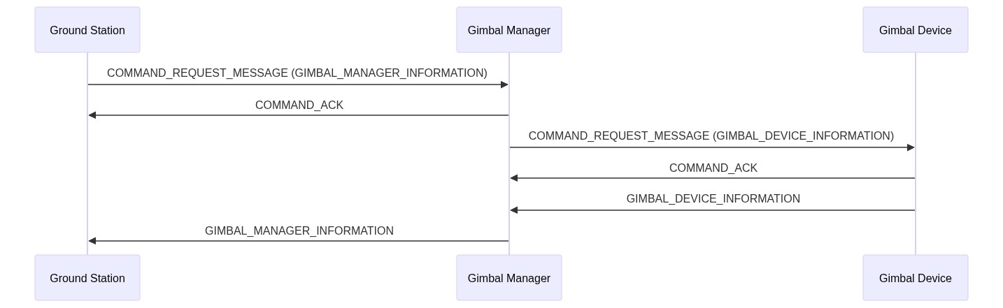
This shows a possible sequence on startup. Note that the gimbal manager could already discover the gimbal device before the ground station asks for the information.
Normal Manual Control
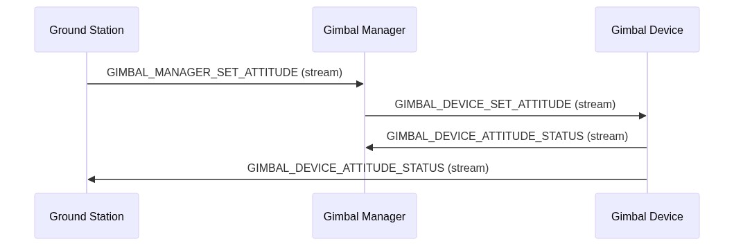
During the normal manual control, all messages are streamed at a regular rate. Note that GIMBAL_DEVICE_ATTITUDE_STATUS is broadcast to anyone, so to the gimbal manager and also the ground station.
ROI Initiated from Ground Station
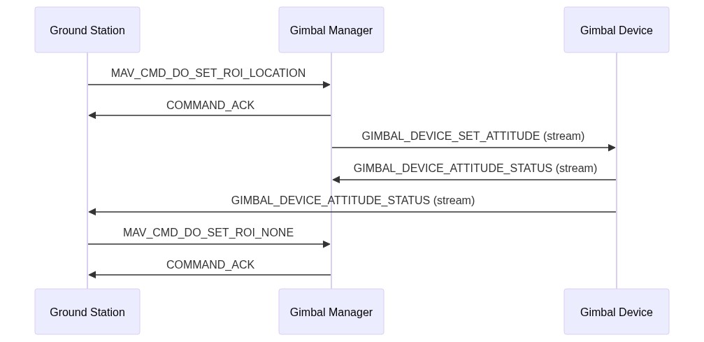
ROI can be started using a command and should also be stopped again with a command. The ROI command is translated to a gimbal attitude in the gimbal manager.
Attitude Set During Mission

In this case the gimbal manager is implemented by the autopilot which "sends" the attitude command (for instance for a survey).
How to Implement the Gimbal Device Interface
Below is a short summary of all messages that a gimbal device should implement.
INFO
A Gimbal Device can be tested by connecting it to an autopilot with a Gimbal Manager. To avoid having to do a full setup including autopilot, a direct test using MAVSDK is available.
Messages to Send
The messages listed should be broadcast on the network/on all connections (sent to everyone).
HEARTBEAT
Heartbeats should always be sent (usually at 1 Hz).
INFO
Gimbals that set their sysid from the autopilot will need to wait for the autopilot's heartbeat before emitting their own (note that if the gimbal can receive heartbeats from multiple autopilots then the sysid must be explicitly/statically configured).
sysid: the same sysid as the autopilot (this can either be done by configuration, or by listening to the autopilot's heartbeat first and then copying the sysid, default: 1)compid: MAV_COMP_ID_GIMBALtype: MAV_TYPE_GIMBALautopilot: MAV_AUTOPILOT_INVALIDbase_mode: 0custom_mode: 0system_status:MAV_STATE_UNINIT
GIMBAL_DEVICE_ATTITUDE_STATUS
The gimbal device should send out its attitude status at a regular rate, e.g. 10 Hz. The fields target_system and target_component can be set to 0 (broadcast) by default.
GIMBAL_DEVICE_INFORMATION
The static information about the gimbal device needs to be sent out when requested using MAV_CMD_REQUEST_MESSAGE.
Messages to Listen To/Handle
GIMBAL_DEVICE_SET_ATTITUDE
This is the actual attitude setpoint that the gimbal device should follow. Note that the frame of the quaternion setpoint depends on the GIMBAL_DEVICE_FLAGS.
AUTOPILOT_STATE_FOR_GIMBAL_DEVICE
The gimbal device should be able to get all the information from the autopilot that it requires in this one message. If something is missing that should be streamed at a high rate, it should be added to this message.
If this message is not sent by default by the autopilot, or the rate is not ok, the command MAV_CMD_SET_MESSAGE_INTERVAL can be used to request it at a certain rate.
COMMAND_LONG
The gimbal device needs to check for commands. See below which commands should get answered.
Commands to Answer
MAV_CMD_REQUEST_MESSAGE
The gimbal device should send out messages when they get requested, e.g. GIMBAL_DEVICE_INFORMATION.
MAV_CMD_SET_MESSAGE_INTERVAL
The gimbal device should stream messages at the rate requested.